
This section addresses the requirements for thermal control of the opaque portion of the building shell or envelope. Fenestration, windows, skylights, and glazed doors are addressed in Section 3.3.
Opaque elements of the building envelope contribute significantly to the energy efficiency of the building and its design intent. Components of the building shell include the walls, floor, the roof or ceiling, doors, and fenestration. Definitions for fenestration are addressed in Section 3.3.
Envelope and other building components definitions are listed in §100.1(b) of the Energy Code and the Reference Joint Appendices JA1.

Source: California Energy Commission
Opaque envelope assemblies are made up of a variety of components, such as wood or metal framing, masonry or concrete, insulation, and other membranes for moisture and/or fire protection and may have a variety of interior and exterior sheathings even before the final exterior façade is placed. Correctly calculating assembly U-factors is critical to the selection of equipment to meet the heating and cooling loads of the building. Performance compliance software automatically calculates the thermal effects of component layers making up the envelope assembly, but software programs may use different user input hierarchies. The Reference Joint Appendices JA4, “U-factor, C-factor, and Thermal Mass Data,” provide detailed thermal data for many wall, roof/ceiling, and floor assemblies. However, JA4 cannot cover every possible combination of materials and thickness that might be used in a building. For this reason, the Energy Commission has incorporated into the public domain software CBECC-COM, a program for calculating material properties of typical envelope assemblies which are not found in JA4.
Key terms of assembly thermal performance are:
- R-value = hr x ft2 x °F/Btu
- R = inches of thickness/k
- U-factor = Btu/(hr x ft2 x °F)
- k = Btu x in/(hr x ft2 x °F)
- C = Btu/(hr. x ft2 x °F) or C = k/inches of thickness
This section contains mandatory requirements that are not specific to one envelope component.
Manufacturers must certify that insulating materials comply with the California Quality Standards for Insulating Materials, which became effective January 1, 1982. It ensures that insulation sold or installed in the state performs according to the stated R-value and meets minimum quality, health, and safety standards.
Builders may not install insulating materials, unless the product has been certified by the Department of Consumer Affairs, Bureau of Electronic and Appliance Repair, Home Furnishing and Thermal Insulation. Builders and enforcement agencies shall use the Department of Consumer Affairs Directory of Certified Insulation Materials to verify certification of the insulating material. If an insulating product is not listed in the most recent edition of the directory, contact the Department of Consumer Affairs, Bureau of Household Goods and Services, at (916) 999-2041 or by email: HomeProducts@dca.ca.gov.
The mandatory requirements restrict the use of urea formaldehyde foam insulation. The restrictions are intended to limit human exposure to formaldehyde, which is a volatile organic chemical known to be harmful to humans.
If foam insulation is used that has urea formaldehyde, it must be installed on the exterior side of the wall (not in the cavity of framed walls), and a continuous barrier must be placed in the wall construction to isolate the insulation from the interior of the space. The barrier must be 4-mil (0.1 mm) thick, polyethylene or equivalent.
The California Quality Standards for Insulating Materials requires that all exposed installations of faced mineral fiber and mineral aggregate insulations use fire-retardant facings that have been tested and certified not to exceed a flame spread index of 25 and a smoke development index of 450. Insulation facings that do not touch a ceiling, wall, floor surface, and faced batts on the underside of roofs with an air space between the ceiling and facing are considered exposed applications. Flame spread index and smoke density index are shown on the insulation or packaging material or may be obtained from the manufacturer.
All joints and other openings in the building envelope that are potential sources of air leakage must be caulked, gasketed, weather stripped, or otherwise sealed to limit air leakage. This applies to roof penetrations and to penetrations for pipes and conduits, ducts, vents, and other openings in the building envelope. Particular attention should be paid to the junctures where assemblies meet, and all gaps between wall panels, around doors, and other construction joints. Ceiling joints, lighting fixtures, and rough openings for doors and windows should all be considered potential sources of unnecessary energy loss due to infiltration. No special construction requirements are necessary for suspended (T-bar) ceilings, provided they meet the requirements of §110.7.
Newly constructed nonresidential and hotels/motel buildings must meet mandatory insulation requirements for opaque portions of the building that separate conditioned spaces from unconditioned spaces or ambient air.
See the sections on roof, walls, doors, and floors
-
An exception is specified that exempts buildings designed as data centers with high, constant server loads from the mandatory minimum requirements. To qualify for this exception, the building should have a design computer room process load of 750 kW or greater.
The 2022 Energy Code requires that the air barrier is clearly detailed on construction documents and that acceptable air barrier materials are used. Verification is carried out by blower door testing – this measurement procedure is described in Nonresidential Appendix NA5.
Construction documents shall include details, notes, or specifications to clearly identify air barrier boundaries, interconnections, penetrations, and associated square foot calculations for all sides of the air barrier.
TABLE 140.3-B of the Energy Code specifies material requirements for air barriers in nonresidential buildings. Air barrier requirements apply to nonresidential buildings, but not relocatable public school buildings, and cannot be traded off in the performance approach. These requirements reduce the overall building air leakage rate. The reduction in air leakage can be met with a continuous air barrier that seals all joints and openings in the building envelope and is composed of one of the following:
- Materials having a maximum air permeance of 0.004 cfm/ft² (see Table 3-1).
- Assemblies of materials and components having an average air leakage not exceeding 0.04 cfm/ft².
- An entire building having an air leakage rate not exceeding 0.40 cfm/ft2.
The air leakage requirements stipulated in §140.3 must be met, either by demonstrating that component air leakage of 0.04 cfm/ft2 or the whole-building air leakage of 0.4 cfm/ft² is not exceeded.
MATERIALS AND THICKNESS |
Plywood – min. 3/8 inches thickness |
Oriented strand board – min. 3/8 inches thickness |
Extruded polystyrene insulation board – min. ½ inches thickness |
Foil-back polyisocyanurate insulation board – min. ½ inches thickness |
Closed- cell spray foam with a minimum density of 2.0 pcf and a min. 1½2.0 inches thickness |
Open cell spray foam with a density no less than 0.4 pcf and no greater than 1.5 pcf, and a min. 5½ inches thickness |
Exterior or interior gypsum board min. ½ inches thickness |
Cement board – min. ½ inches thickness |
Built-up roofing membrane |
Modified bituminous roof membrane |
Fully adhered single-ply roof membrane |
A Portland cement or Portland sand parge, or a gypsum plaster, each with min. 5/8 inches thickness |
Cast-in-place concrete, or precast concrete |
Fully grouted concrete block masonry |
Sheet steel or sheet aluminum |

Source: California Statewide CASE Team

Sample of Pre-Test Coordination Steps (Performed by Testing Agency)

Note –all items represented in red are to be confirmed with project design team and fan manufacturer. This example is not related to the images in the rest of the appendix
Source: California Statewide CASE Team
 indicated on plan. Provided by testing agency")

The testing agency shall perform a pre-test inspection in accordance with Nonresidential Appendix NA5.3 in coordination with the general contractor (GC) and direct the GC to complete the pre-test setup in accordance with Nonresidential Appendix NA5.3.
Test Execution (Performed by Testing Agency)
- Deliver equipment in accordance with test plan.
- Perform site walk with general contractor (GC) to perform final assessment of building and temporary sealing measures (identified during pretest meetings and in GC setup guidelines). Identify all areas of incomplete or damaged envelope areas that could potentially affect the result of the air leakage test.
- Confirm that access through fan station set up openings is restricted for other trades. Identify pathways of which wires and tubes will be run such that the GC can assess and mitigate safety hazards and damages to equipment accordingly.
- Perform setup of fan stations:
- Ensure that doorway(s) the blower door panel is set within is sealed around the perimeter to reduce the amount of air loss through the opening.
- Confirm that all stations are setup with fans in the correct direction of airflow (inward for pressurization, outward for depressurization).
- Reference tubes used to measure pressure differential across the building envelope should be placed out of paths of significant airflow.
- Coordinate a temporary shutdown with GC of access to the building to perform preliminary test on building. During this preliminary test, fans should be ramped up to attempt to achieve target pressure for the air leakage test. Based off of the pressure obtained, the testing agency should be able to assess if preparation work of the building needs to be further reviewed.
- If the schedule allows, coordinate a walkthrough with the GC with the building under pressure to determine if any intentional openings were not properly sealed or secured.
- If infrared scanning equipment is available, perform a scan of building to assist in identifying any air leakage out of unintentional openings and intentional openings that were not properly sealed or secured.
- Following the preliminary test, testing agency should also assess if adjustments to station setups are required to improve pressure distribution and flow readings. Changes to the test setup should be documented for the record.
- Once the preliminary test has been completed and any repairs to the preparation work have been completed, testing agency to complete the test in accordance with Nonresidential Appendix NA5.5 of the Energy Standards and ASTM E3158. Upon collection of data points in accordance with ASTM E3158, the testing agency should be able to determine an approximate air leakage per envelope area based off of building inputs (envelope area, temperature differential, wind speeds height above elevation, etc.). The testing agency should then confirm this value using the fan manufacturer’s software with the GC to determine if the building passed the test.
- If the building failed the test, perform reviews using methods of Nonresidential Appendix NA5.7 and ASTM E1186.
Metal Building: Weighted average U-factor of U-0.098 (R-19 screw down roof, no thermal blocks).
Wood-Framed and Others: Weighted average U-factor of U-0.075 (2x4 rafter, R-19 insulation).
Insulation installed on top of suspended (T-bar) ceilings with removable ceiling panels may not be used to comply with the Energy Code unless the installation meets the criteria described in the Exception to §120.7(a)3 below. Insulation may be installed in this location for other purposes such as for sound control, but it will have no value in terms of meeting roof/ceiling insulation requirements of the Energy Code.
Acceptable insulation installations include placing the insulation in direct contact with a continuous roof or ceiling that is sealed to limit infiltration and exfiltration as specified in §110.7, including, but not limited to, placing insulation either above or below the roof deck or on top of a drywall ceiling.
When insulation is installed at the roof in nonresidential buildings, the space between the ceiling and the roof is considered either directly or indirectly conditioned space. Therefore, this space must not include fixed vents or openings to the outdoors or to unconditioned spaces. This space is not considered an attic for complying with California Building Code (CBC) attic ventilation requirements. Vents that do not penetrate the roof deck and that are designed for wind resistance for roof membranes are acceptable.
-
Exception to §120.7(a)3: When there are conditioned spaces with a combined floor area no greater than 2,000 square feet in an otherwise unconditioned building, and when the average height of the space between the ceiling and the roof over these spaces is greater than 12 feet, insulation placed in direct contact with a suspended ceiling with removable ceiling panels shall be an acceptable method of reducing heat loss from a conditioned space and shall be accounted for in heat loss calculations.
Wet insulation systems are roofing systems where the insulation is installed above the roof’s waterproof membrane. Water can penetrate this insulation material and affect the energy performance of the roofing assembly in wet and cool climates. In climate zones 1 and 16, the insulating R-value of continuous insulation materials installed above the waterproof membrane of the roof must be multiplied by 0.8 before choosing the table column in Reference Joint Appendix JA4 for determining assembly U-factor. See the footnotes in JA4 for Tables 4.2.1 through 4.2.7.
In general, light-colored, high-reflectance surfaces reflect solar energy (visible light, invisible infrared, and ultraviolet radiation) and stay cooler than darker surfaces that absorb the sun’s energy and become heated. The Energy Code prescribes cool roof radiative properties for low-sloped and steep-sloped roofs. Low-sloped roofs receive more solar radiation than steep-sloped roofs in the summer when the sun is higher in the sky.
Roofing products must be tested and labeled by the Cool Roof Rating Council (CRRC), and liquid-applied products must meet minimum standards for performance and durability per §110.8(i)4. When installing cool roofs, the aged solar reflectance and thermal emittance of the roofing product must be tested and certified according to CRRC procedures. The aged solar reflectance and thermal emittance properties are rated and listed by the Cool Roof Rating Council at www.coolroofs.org. When a CRRC rating is not obtained for the roofing products, the Energy Code default values for solar reflectance and thermal emittance must be used.
When a cool roof is installed to meet the prescriptive requirement or when it is used for compliance credit, the products must be tested and labeled by the CRRC as specified in §10-113. The CRRC is the supervisory entity responsible for certifying cool roof products. The CRRC test procedure is documented in CRRC-1, the CRRC Product Rating Program Manual. This test procedure includes tests for both solar reflectance and thermal emittance. See Figure 3-4 for an example of an approved CRRC product label.
Figure 3-4: Sample CRRC Product Label and Information

2. Solar Reflectance, Thermal Emittance, and Solar Reflectance Index (SRI)
Both solar reflectance and thermal emittance are measured from 0 to 1; the higher the value, the "cooler" the roof. There are numerous roofing materials in a wide range of colors that have adequate cool roof properties. Excess heat can increase the air-conditioning load of a building, resulting in increased air-conditioning energy needed for maintaining occupant comfort. High-emitting roof surfaces reject absorbed heat quickly (upward and out of the building) than roof surfaces with low-emitting properties.
Solar Reflectance (SR). There are three measurements of solar reflectance:
-
Initial solar reflectance
-
Three-year aged solar reflectance
-
Accelerated aged solar reflectance
All requirements of the Energy Code are based on the three-year aged solar reflectance. If the aged value for the reflectance is not available in the CRRC’s Rated Product Directory, then the aged value shall be derived from the CRRC initial value or an accelerated testing process. Until the appropriate age-rated value for the reflectance is posted in the directory, or a new method of testing is used to find the accelerated solar reflectance, the equation below can be used to calculate the aged rated solar reflectance.
-
Aged Reflectancecalculated = (0.2+ β[ρinitial – 0.2])
-
Where,
-
ρinitial = Initial reflectance listed in the CRRC Rated Product Directory
-
β= 0.65 for field-applied coating, or 0.70 for not a field-applied coating
Thermal Emittance. The Energy Code does not distinguish between initial and aged thermal emittance, meaning that either value can be used to demonstrate compliance with the Energy Code.
Default Values. If a manufacturer fails to obtain CRRC certificate for its roofing products, the following default aged solar reflectance and thermal emittance values must be used for compliance:
a. For asphalt shingles, 0.08/0.75.
b. For all other roofing products, 0.10/0.75.
Solar Reflectance Index (SRI). The temperature of a surface depends on the solar radiation incidence, surface reflectance, and emittance. The SRI measures the relative steady-state surface temperature of a surface with respect to standard white (SRI=100) and standard black (SRI=0) under the standard solar and ambient condition. A calculator has been produced that calculates the SRI by designating the solar reflectance and thermal emittance of the desired roofing material. The calculator can be found at http://www.energy.ca.gov/title24/2022standards. To calculate the SRI, either the initial or the three-year aged solar reflectance value of the roofing product may be used. By using the SRI calculator, a cool roof may comply with a lower emittance, as long as the aged solar reflectance is higher and vice versa.
There are several liquid products, including elastomeric coatings and white acrylic coatings that qualify for field-applied liquid coatings. The Energy Code specifies minimum performance and durability requirements for field-applied liquid coatings in Table 110.8-C depending on the type of coating. These requirements do not apply to industrial coatings that are factory-applied, such as metal roof panels. The requirements address elongation, tensile strength, permeance, and accelerated weathering.
Aluminum-pigmented coatings are silver-colored coatings that are commonly applied to modified bitumen and other roofing products. The coating has aluminum pigments that float to the surface of the coating and provides a shiny, surface. Because of the shiny surface and the physical properties of aluminum, these coatings have a thermal emittance below 0.75, which is the minimum rating for prescriptive compliance. The performance approach is typically used to achieve compliance with these coatings.
This class of field-applied liquid coatings shall be applied across the entire surface of the roof and meet the dry mil thickness or coverage recommended by the coating manufacturer, taking into consideration the substrate on which the coating will be applied. Also, the aluminum-pigmented asphalt roof coatings shall be manufactured in accordance with ASTM D2824.1 Standard specification is also required for aluminum-pigmented asphalt roof coatings, nonfibered, asbestos-fibered, and fibered without asbestos that are suitable for applying to roofing or masonry surfaces by brush or spray. Use ASTM D6848, Standard Specification for Aluminum Pigmented Emulsified Asphalt used as a Protective Coating for Roofing, installed in accordance with ASTM D38052, Standard Guide for Application of Aluminum-Pigmented Asphalt Roof Coatings.
This class of coatings consists of a layer of cement and has been used for several years in California’s Central Valley and other regions. These coatings may be applied to almost any type of roofing product. Cement-based coatings shall be applied across the entire roof surface to meet the dry mil thickness or coverage recommended by the manufacturer. Also, cement-based coatings shall be manufactured to contain no less than 20 percent Portland cement and meet the requirements of ASTM D8223, ASTM C1583, and ASTM D5870.
Other field-applied liquid coatings include elastomeric and acrylic-based coatings. These coatings must be applied across the entire surface of the roof to meet the dry mil thickness or coverage recommended by the coating manufacturer, taking into consideration the substrate on which the coating will be applied. The field-applied liquid coatings must be tested to meet performance and durability requirements as specified in Table 110.8-C of the Energy Code or the minimum performance requirements of ASTM C836, D3468, D6083, or D6694, whichever are appropriate to the coating material.
1 A. This specification covers asphalt-based, aluminum roof coatings suitable for application to roofing or masonry surfaces by brush or spray.
B. The values stated in SI units are to be regarded as the standard. The values in parentheses are for information only.
C. The following precautionary caveat pertains only to the test method portion, Section 8, of this specification: This standard does not purport to address all of the safety concerns, if any, associated with its use. It is the responsibility of the user of this standard to establish appropriate safety and health practices and determine the applicability of regulatory limitations prior to use.
2 A. This guide covers the application methods for Specification D 2824 Aluminum-Pigmented Asphalt Roof Coatings, Non-Fibered (Type I), Asbestos Fibered (Type II), and Fibered without Asbestos (Type III), for application on asphalt built-up roof membranes, modified bitumen roof membranes, bituminous base flashings, concrete surfaces, metal surfaces, emulsion coatings, and solvent-based coatings. This guide does not apply to the selection of a specific aluminum- pigmented asphalt roof coating type for use on specific projects.
B. The values stated in SI units are to be regarded as the standard. The values given in parentheses are for information only.
C. This standard does not purport to address all of the safety concerns, if any, associated with its use. It is the responsibility of the user of this standard to establish appropriate safety and health practices and determine the applicability of regulatory limitations prior to use. Specific precautionary statements are given in Section 4.
3 A. This guide is intended for the evaluation of clear and pigmented coatings designed for use on rigid or semi rigid plastic substrates. Coated film and sheeting are not covered by this guide.
B. This standard does not purport to address all of the safety concerns, if any, associated with its use. It is the responsibility of the user of this standard to establish appropriate safety and health practices and determine the applicability of regulatory limitations prior to use.
§140.3(a)1A, TABLES 140.3-B, C, D
The prescriptive requirements call for roofing products to meet the aged solar reflectance and thermal emittance in both low-sloped and steep-sloped roof applications for nonresidential buildings. A qualifying roofing product under the prescriptive approach for a nonresidential building must have an aged solar reflectance and thermal emittance greater than or equal to that the values indicated in TABLE 140.3-B of the Energy Code. Table 3-2 is for hotel/motel guest rooms, and Table 3-3 is for relocatable public-school buildings where the manufacturer certifies use in all climate zones.
|
Climate Zones
|
1
|
2
|
3
|
4
|
5
|
6
|
7
|
8
|
9
|
10
|
11
|
12
|
13
|
14
|
15
|
16
|
|
Low Sloped Aged Reflectance
|
0.63
|
0.63
|
0.63
|
0.63
|
0.63
|
0.63
|
0.63
|
0.63
|
0.63
|
0.63
|
0.63
|
0.63
|
0.63
|
0.63
|
0.63
|
0.63
|
|
Low Sloped Emittance
|
0.75
|
0.75
|
0.75
|
0.75
|
0.75
|
0.75
|
0.75
|
0.75
|
0.75
|
0.75
|
0.75
|
0.75
|
0.75
|
0.75
|
0.75
|
0.75
|
|
Low Sloped SRI
|
75
|
75
|
75
|
75
|
75
|
75
|
75
|
75
|
75
|
75
|
75
|
75
|
75
|
75
|
75
|
75
|
|
Steep Sloped Aged Reflectance
|
0.20
|
0.25
|
0.20
|
0.25
|
0.25
|
0.25
|
0.25
|
0.25
|
0.25
|
0.25
|
0.25
|
0.25
|
0.25
|
0.25
|
0.25
|
0.25
|
|
Steep Sloped Emittance
|
0.75
|
0.80
|
0.75
|
0.80
|
0.80
|
0.80
|
0.80
|
0.80
|
0.80
|
0.80
|
0.80
|
0.80
|
0.80
|
0.80
|
0.80
|
0.80
|
|
Steep Sloped SRI
|
16
|
23
|
23
|
23
|
23
|
23
|
23
|
23
|
23
|
23
|
23
|
23
|
23
|
23
|
23
|
23
|
Energy Code, Table 140.3-B
| Climate Zone (CZ) | Low-sloped Aged Reflectance | Low-sloped Emittance | Low-sloped SRI | Steep-Sloped Aged Reflectance | Steep-Sloped Emittance | Steep-Sloped SRI |
| CZ 1 | NR | NR | NR | NR | NR | 16 |
| CZ 2 | NR | NR | NR | 0.20 | 0.75 | 16 |
| CZ 3 | NR | NR | NR | 0.20 | 0.75 | 16 |
| CZ 4 | NR | NR | NR | 0.20 | 0.75 | 16 |
| CZ 5 | NR | NR | NR | 0.20 | 0.75 | 16 |
| CZ 6 | NR | NR | NR | 0.20 | 0.75 | 16 |
| CZ 7 | NR | NR | NR | 0.20 | 0.75 | 16 |
| CZ 8 | NR | NR | NR | 0.20 | 0.75 | 16 |
| CZ 9 | 0.55 | 0.75 | 64 | 0.20 | 0.75 | 16 |
| CZ 10 | 0.55 | 0.75 | 64 | 0.20 | 0.75 | 16 |
| CZ 11 | 0.55 | 0.75 | 64 | 0.20 | 0.75 | 16 |
| CZ 12 | NR | NR | NR | 0.20 | 0.75 | 16 |
| CZ 13 | 0.55 | 0.75 | 64 | 0.20 | 0.75 | 16 |
| CZ 14 | 0.55 | 0.75 | 64 | 0.20 | 0.75 | 16 |
| CZ 15 | 0.55 | 0.75 | 64 | 0.20 | 0.75 | 16 |
| CZ 16 | NR | NR | NR | NR | NR | 16 |
Energy Code, Table 140.3-C
|
Roofing Products
|
Aged Reflectance
|
Emittance
|
|
Low-Sloped
|
0.63
|
0.75
|
|
SRI
|
75
|
75
|
|
Steep-Sloped
|
0.25
|
0.80
|
|
SRI
|
23
|
23
|
Energy Code, Table 140.3-D
Exceptions to the minimum prescriptive requirements for solar reflectance and thermal emittance:
-
Roof area covered by building-integrated photovoltaic panels and building-integrated solar thermal panels is not required to meet the cool roof requirements.
-
If the roof construction has a thermal mass like gravel, concrete pavers, stone, or other materials with a weight of at least 25 lb/ft² over the roof membrane, then it is exempt from the above requirements for solar reflectance and thermal emittance.
-
Wood-framed roofs in Climate Zones 3 and 5 with a U-factor of 0.034 are exempt from the low-sloped cool roof requirement.
Where a low-sloped nonresidential roof’s aged reflectance is less than the prescribed requirement, insulation tradeoffs are available. By increasing the insulation level of a roof, a roofing product with a lower reflectance than the prescriptive requirements can be used to meet the cool roof requirements. The appropriate U-factor can be determined from Table 3-4 for nonresidential buildings based on roof type, climate zone and aged reflectance of at least 0.25.
Aged Solar Reflectance | Metal Building Climate Zone 1-16 U-factor | Wood-Framed and Other Climate Zone 6, 7, and 8 U-factor | Wood Framed and Other All Other Climate Zones U-factor |
0.62-0.56 | 0.038 | 0.039 | 0.029 |
0.55-0.46 | 0.035 | 0.036 | 0.028 |
0.45-0.36 | 0.033 | 0.033 | 0.027 |
0.35 -0.25 | 0.031 | 0.032 | 0.026 |
Energy Code, Table 140.3
§140.3(a)1B, TABLES 140.3-B, C, D
Under the prescriptive requirements, roofs or ceilings must have an assembly U-factor equal to or lower than the U-factor criterion for nonresidential l buildings. (See Table 3-5.) The U-factor values for exterior roofs and ceilings from Reference Appendices, Joint Appendix JA4 must be used to determine compliance with the maximum assembly U-factor requirements. Alternatively, the assembly calculator that is incorporated into the approved energy modeling software, can be used to determine U-factors for assemblies and/or components not listed in JA4 tables.
The prescriptive requirement for metal building roofs requires the entire cavity be filled with insulation. A common technique for standing seam metal roofs is to drape a layer of insulation over the purlins, using thermal blocks where the insulation is compressed at the supports. (See Figure 3-3A.) Either approach on insulation may be used in the performance approach. However, there are significant benefits to using the “filled cavity” approach as shown in Figure 3-3B.

Source: North American Insulation Manufacturers Association (NAIMA)

Source: North American Insulation Manufacturers Association (NAIMA)
A rigid polyisocyanurate (“polyiso”) thermal block with a minimum R-value of R-3.5 should be installed at the supports (a 1-inch-thick thermal block is recommended). The first rated R-value of the insulation is for faced insulation installed between the purlins. The second rated R-value of insulation represents unfaced insulation installed above the first layer, perpendicular to the purlins and compressed when the metal roof panels are attached. A supporting structure retains the bottom of the first layer at the prescribed depth required for the full thickness of insulation.
The bottom layer of insulation should completely fill the space between the purlins, and the support bands should be installed tightly to prevent the insulation from sagging.
The configuration in Figure 3-3B shown with two layers, one of R-19 and one of R-10 insulation, corresponds to the prescriptive requirement of U-0.041. ,Other insulation combinations exceeding the minimum requirement are readily achievable.
§10-113, §140.1, TABLE 140.3
Compliance options for roofing products and insulation. See Section 3.5 and Chapter 12 for more on the performance approach.
Example 3-1
Question:
According to the provisions of the Energy Code, are cool roofs mandatory for nonresidential buildings?
Answer:
No. Cool roofs are not mandatory. The prescriptive compliance requirements depend on the climate zone, building type and roof slope. Compliance with aged solar reflectance and thermal emittance, or SRI is required per Energy Code, TABLES 140.3-B, C, and D. In the performance approach, reflectance, and emittance values less than the minimum prescriptive requirements may be used; however, any deficit that results from this choice must be made up by improving other energy efficiency features in the building, which include envelope, space-conditioning system, and lighting systems.
Example 3-2
Question:
Must all roofing materials used in California, whether cool roof or not, be certified by the CRRC and labeled accordingly?
Answer:
Yes, when altering your roof, such as a new reroof or replacement of 50 percent or 2,000ft², whichever is less, then, either the prescriptive envelope component approach or the performance approach can be used for compliance. In these cases, the roof must be certified and labeled by the Cool Roof Rating Council (CRRC) for nonresidential roofs. If you are using the performance approach to receive compliance credit, you can either obtain a CRRC certification, or use a default solar reflectance of 0.10 and thermal emittance of 0.75. Using default values instead of CRRC certificates may result in a significant energy penalty that must be made up by increasing energy efficiency in other building features. The default solar reflectance for asphalt shingles is 0.08.
However, in the case of a roof repair, such as for a leak, the roofing product does not need to be a cool roof nor certified by the CRRC.
Example 3-3
Question:
Can I use aged solar reflectance and thermal emittance data generated by any nationally recognized and well-respected laboratory in lieu of CRRC ratings? Can in-house testing by the manufacturer be used to qualify my product?
Answer:
No. Only CRRC ratings from the product directory list can be used to establish cool roof product qualification for standards compliance. The CRRC process requires use of a CRRC-accredited laboratory (under most circumstances, an "Accredited Independent Testing Laboratory (AITL) defined by the CRRC program.) Any testing laboratory can become an AITL by following the CRRC accreditation process and satisfying the requirements. The roster of CRRC-accredited laboratories is posted on the CRRC website (http://www.coolroofs.org).
Example 3-4
Question:
Can the reflectance and emittance requirements of ENERGY STAR® cool roofs be substituted for standards requirements?
Answer
No. Only roofing products which are listed by the CRRC in its Rated Product Directory can be used to comply with the Standards. CRRC is the only organization that has met the criteria set in §10-113.
Example 3-5
Question:
Can I claim to have a cool roof, or can I get anything higher than a default reflectance, if my roof does not meet the field-applied coating performance requirements of the Energy Code?
Answer:
No, you cannot claim to have a cool roof and you cannot claim higher energy credits if your roof does not meet the coating performance requirements of the Energy Code for field-applied coatings.
Example 3-6
Question:
How does a product get CRRC cool roof certification?
Answer:
Any party wishing to have a product or products certified by CRRC should contact the CRRC toll-free (866) 465-2523 from inside the United States or (510) 482-4420, ext. 215, or email info@coolroofs.org. In addition, CRRC publishes the procedures in the CRRC-1 Program Manual, available for free on http://www.coolroofs.org or by calling the CRRC. Working with CRRC staff is strongly recommended.
Example 3-7
Question:
Do alterations to the roof of an unconditioned building trigger cool roof requirements?
Answer:
No, alterations to the roof of an unconditioned building do not trigger cool roof requirements. In general, the lighting requirements are the only requirements applicable for both newly constructed and altered unconditioned buildings; this includes §140.3(c), the skylight requirements. Building envelope (other than skylight requirements) and space-conditioning requirements do not apply to unconditioned buildings.
Example 3-8
Question:
What happens if I have a low-sloped roof on most of my buildings and steep-sloped roof on another portion of the roof? Do I have to meet the two different sets of rules in §140.3(a)1Ai and ii?
Answer:
Yes, your building would have to meet both the low-sloped requirement and the steep-sloped roof requirements for the respective areas.
Example 3-9
Question:
I am installing a green/garden roof (roofs whose surface is composed of soil and plants) on top of an office building. Although green/garden roofs are not cool roofs by their reflectance properties, will they be allowed under the Energy Code?
Answer:
Yes, the Energy Commission considers a green/garden roof as a roof with thermal mass on it.
Under Exception 4 to §140.3(a)1Ai, if a garden roof has a dry unit weight of 25 lb/ft², then the garden roof is equivalent to cool roof.
The U-factor criteria for walls depend on the class of construction. U-factors used for compliance must be selected from Reference Appendices, Joint Appendix JA4. Alternatively, the assembly calculator that is incorporated into California Building Energy Code Compliance (CBECC) software can be used to determine U-factors for assemblies and/or components not listed in JA4.
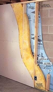
There are five common classes of wall constructions: wood-framed, metal-framed, metal building walls, light mass, and heavy mass. (Figure 3-5.) The following provides information about these wall systems, as well as furred walls, spandrel panels and opaque curtain walls:
Note: For light- and high-mass walls, heat capacity (HC) is the amount of heat required to raise the temperature of the material by 1 degree F. In the Energy Code, it is defined as the product of the density (lb/ft3), specific heat (Btu/lb-F), and wall thickness (ft). For instance, a 6” medium weight concrete hollow unit masonry wall has a heat capacity of 8.4 and is considered a light mass wall. The same masonry wall with solid grout that is 10 inches thick has a heat capacity of 19.7 and is considered a heavy mass wall.
Uprop = 1 / [ (1/Ucol,A) + Rcont,insul]
Example 3-10
Question :
An 8-inch (20 cm) medium-weight concrete block wall with uninsulated cores has a layer of 1 inch (25 mm) thick exterior polystyrene continuous insulation with an R-value of R-5. What is the U-factor for this assembly?
Answer:
From Reference Appendices, Joint Appendix Table 4.3.5, the U-factor for the block wall is 0.53. From Equation 4-1, the U-factor is calculated as:
U= 1 / [ (1/0.53) + 5] = 0.145

In addition to the mandatory requirements in §110.8 for all buildings, Nonresidential, high–rise residential, hotels and motels must also meet the requirements in §120.7
The opaque portions of walls that separate conditioned spaces from unconditioned spaces or ambient air shall meet these applicable requirements.
-
Metal Building: Weighted average U-factor of U-0.113 (single layer of R-13 batt insulation).
-
Metal-Framed: Weighted average U-factor of U-0.151 (R-8 continuous insulation, or R-13 batt insulation between studs and 1/2” of continuous rigid insulation of R-2). It may be possible to meet the area-weighted average U-factor without continuous insulation if the appropriate siding materials are used.
-
Light Mass Walls: 6 inches or greater hollow core concrete masonry unit having a U-factor not exceeding 0.440 (partially grouted with insulated cells).
-
Heavy Mass Walls: 8 inches or greater hollow core concrete masonry unit having a U-factor not exceeding 0.690 (solid grout concrete, normal weight, 125 lb/ft3).
-
Wood-Framed and Others: Weighted average U-factor of U-0.110 (R-11 batt insulation).
-
Spandrel Panels and Curtain Wall: Weighted average U-factor of U-0.280.
Exception to Section 120.7: Buildings designed as data centers with high, constant server loads are exempt from the mandatory minimum requirements. To qualify for this exception, it should have a design computer room process load of 750 kW or greater.
§140.3(a)2, TABLE 140.3-B, C, D
Under the prescriptive requirements, exterior walls must have an assembly U-factor equal to or lower than the U-factor criterion for nonresidential buildings in TABLE 140.3-B, C, D (see Table 3-6).
The U-factor for exterior walls from Reference Appendices, Joint Appendix JA4 must be used to determine compliance with the assembly U-factor requirements. The Energy Code does not allow using the R-value of the cavity or continuous insulation alone to demonstrate compliance with the insulation values of Reference Appendices, Joint Appendix JA4; only U-factors may be used to demonstrate compliance.
For metal-framed walls with insulation between the framing sections, continuous insulation may need to be added to meet the U-factor requirements of the Energy Code. For light mass walls, insulation is not required for buildings in South Coast climates (i.e., climate zones 5-9) but is required for other climates. For heavy mass walls, insulation is not required for buildings in Central Coast (i.e., climate zones 3-5) or South Coast (i.e., climate zones 6-9) climates but is required for other climates.
Climate Zones | 1 | 2 | 3 | 4 | 5 | 6 | 7 | 8 |
Nonresidential Metal Building | 0.113 | 0.061 | 0.113 | 0.061 | 0.061 | 0.113 | 0.113 | 0.061 |
Nonresidential Metal- Frame | 0.060 | 0.055 | 0.071 | 0.055 | 0.055 | 0.060 | 0.060 | 0.055 |
Nonresidential Mass Light | 0.196 | 0.170 | 0.278 | 0.227 | 0.44 | 0.44 | 0.44 | 0.44 |
Nonresidential Mass Heavy | 0.253 | 0.650 | 0.650 | 0.650 | 0.650 | 0.690 | 0.690 | 0.690 |
Nonresidential Wood-Frame | 0.095 | 0.059 | 0.110 | 0.059 | 0.102 | 0.110 | 0.110 | 0.102 |
Hotel/Motel Metal building | 0.061 | 0.061 | 0.061 | 0.061 | 0.061 | 0.061 | 0.061 | 0.061 |
Hotel/Motel Metal -frame | 0.069 | 0.069 | 0.069 | 0.069 | 0.069 | 0.069 | 0.105 | 0.069 |
Hotel/Motel Mass Light | 0.170 | 0.170 | 0.170 | 0.170 | 0.170 | 0.227 | 0.227 | 0.227 |
Hotel/Motel Mass Heavy | 0.160 | 0.160 | 0.160 | 0.184 | 0.211 | 0.690 | 0.690 | 0.690 |
Hotel/Motel Wood-Frame | 0.059 | 0.059 | 0.059 | 0.059 | 0.059 | 0.059 | 0.059 | 0.059 |
Relocatable Public Schools Metal Building | 0.057 | 0.057 | 0.057 | 0.057 | 0.057 | 0.057 | 0.057 | 0.057 |
Relocatable Public Schools Metal -Frame | 0.057 | 0.057 | 0.057 | 0.057 | 0.057 | 0.057 | 0.057 | 0.057 |
Relocatable Public Schools Mass /7.0<HC | 0.170 | 0.170 | 0.170 | 0.170 | 0.170 | 0.170 | 0.170 | 0.170 |
Relocatable Public Schools Wood Frame | 0.042 | 0.042 | 0.042 | 0.042 | 0.042 | 0.042 | 0.042 | 0.042 |
Relocatable Public Schools All Other Walls | 0.059 | 0.059 | 0.059 | 0.059 | 0.059 | 0.059 | 0.059 | 0.059 |
Climate Zones | 9 | 10 | 11 | 12 | 13 | 14 | 15 | 16 |
Nonresidential Metal Building | 0.055 | 0.055 | 0.055 | 0.055 | 0.055 | 0.055 | 0.055 | 0.055 |
Nonresidential Metal- Frame | 0.062 | 0.062 | 0.062 | 0.062 | 0.062 | 0.062 | 0.062 | 0.062 |
Nonresidential Mass Light | 0.44 | 0.170 | 0.170 | 0.170 | 0.170 | 0.170 | 0.170 | 0.170 |
Nonresidential Mass Heavy | 0.690 | 0.650 | 0.184 | 0.253 | 0.211 | 0.184 | 0.184 | 0.160 |
Nonresidential Wood-Frame | 0.059 | 0.059 | 0.045 | 0.059 | 0.059 | 0.059 | 0.042 | 0.059 |
Hotel/Motel Metal building | 0.061 | 0.061 | 0.057 | 0.057 | 0.057 | 0.057 | 0.057 | 0.057 |
Hotel/Motel Metal -frame | 0.069 | 0.069 | 0.069 | 0.069 | 0.069 | 0.069 | 0.048 | 0.069 |
Hotel/Motel Mass Light | 0.196 | 0.170 | 0.170 | 0.170 | 0.170 | 0.170 | 0.170 | 0.170 |
Hotel/Motel Mass Heavy | 0.690 | 0.690 | 0.184 | 0.253 | 0.211 | 0.184 | 0.184 | 0.160 |
Hotel/Motel Wood-Frame | 0.059 | 0.059 | 0.042 | 0.059 | 0.059 | 0.042 | 0.042 | 0.042 |
Relocatable Public Schools Metal Building | 0.057 | 0.057 | 0.057 | 0.057 | 0.057 | 0.057 | 0.057 | 0.057 |
Relocatable Public Schools Metal -Frame | 0.057 | 0.057 | 0.057 | 0.057 | 0.057 | 0.057 | 0.057 | 0.057 |
Relocatable Public Schools Mass /7.0<HC | 0.170 | 0.170 | 0.170 | 0.170 | 0.170 | 0.170 | 0.170 | 0.170 |
Relocatable Public Schools Wood Frame | 0.042 | 0.042 | 0.042 | 0.042 | 0.042 | 0.042 | 0.042 | 0.042 |
Relocatable Public Schools All Other Walls | 0.059 | 0.059 | 0.059 | 0.059 | 0.059 | 0.059 | 0.059 | 0.059 |
§120.7(b)7, §140.3(a)3 and Exception to §140.3(a)5A
Demising walls separate conditioned space from enclosed unconditioned space. The insulation requirements include:
-
Wood-framed: minimum of R-13 insulation (or have an equivalent U-factor of 0.099) between framing members.
-
Metal-framed: minimum R-13 insulation (or a U-factor no greater than 0.151) between framing members plus R-2 continuous insulation.
-
If it is not a framed assembly (constructed of brick, concrete masonry units, or solid concrete), then no insulation is required.
This requirement applies to buildings meeting compliance with either the prescriptive or performance approach.
Note: Window area in demising walls is not counted as part of the window area for this requirement. Demising wall area is not counted as part of the gross exterior wall area or display perimeter for this requirement.
When an exterior door has 25 percent or more glazed area it is considered fenestration. See more on fenestration in Section 3.3.
Manufactured exterior doors shall have an air infiltration rate not exceeding:
-
0.3 cfm/ft2 of door area for nonresidential single doors (swinging and sliding).
-
1.0 cfm/ft2 of door area for nonresidential double doors (swinging).
§140.3(a)7, TABLE 140.3-B, C, D
The Energy Code define prescriptive requirements for exterior doors in TABLE 140.3-B and TABLE 140.3-C. For swinging doors, the maximum U-factor is 0.70, and for non-swinging doors, the maximum allowed U-factor is 1.45 in climate zones 2 through 15 and 0.50 in climate zones 1 and 16. Refer to Energy Code, TABLE 140.3-B, 140.3-C, and 140.3-D for exterior door U-factor requirements.
The swinging door requirement corresponds to uninsulated double-layer metal swinging doors. The 1.45 swinging door U-factor requirement corresponds to insulated single-layer metal doors or uninsulated single-layer metal roll-up doors and fire-rated doors. The 0.50 U-factor requirement for climate zones 1 and 16 corresponds to wood doors with a minimum nominal thickness of 1 ¾ inches. For more information, consult Reference Appendices, Joint Appendix JA4, Table 4.5.1.
When glazing area is 25 percent or more of the entire door area, it is then defined as a fenestration product in the Energy Code, and the entire door area is modeled as a fenestration unit. If the glazing area is less than 25 percent of the door area, the glazing must be modeled as the glass area plus two inches in each direction of the opaque door surface (to account for a frame). However, exterior doors are part of the gross exterior wall area and must be considered when calculating the window to wall ratio.
The U-factor criteria for concrete raised floors depend on whether the floor is a mass floor or not. A mass floor is one constructed of concrete with a heat capacity (HC) greater than or equal to 7.0 Btu/°F-ft².
Insulation levels for nonresidential concrete raised floors with HC ≥ 7.0 using U-factor for compliance, from Reference Appendices, Joint Appendix JA4, Table 4.4.6, are equivalent to no insulation in climate zones 3-10 and associated U-factors to continuous insulation of R-8 in climate zones 1, 2, 11 through 15; and R-15 in climate zone 16.
To determine the U-factor insulation levels for hotel/motel concrete raised floors, use the U-factors that are associated with R-8 continuous insulation in climate zones 7 through 9; R-15 in climate zones 3-5 and 11-13; with additional insulation required in climate zones 1, 2, 14 and 16.
Table 4.4.6 from Reference Appendices, Joint Appendix JA4 is used with mass floors while Tables 4.4.1 through 4.4.5 are used for non-mass floors. (See Figure 3-6.)
Figure 3-6: Classes of Floor Constructions
Heated slab-on-grade floors must be insulated according to the requirements in TABLE 110.8-A of the Energy Code (Table 3-8). The top of the insulation must be protected with a rigid shield to prevent intrusion of insects into the building foundation, and the insulation must be capable of withstanding water intrusion.
A common location for the slab insulation is on the foundation perimeter. Insulation that extends downward to the top of the footing is acceptable. Otherwise, the insulation must extend downward from the level of the top of the slab, down 16 inches (40 cm) or to the frost line, whichever is greater.
For below-grade slabs, vertical insulation shall be extended from the top of the foundation wall to the bottom of the foundation (or the top of the footing) or to the frost line, whichever is greater.
Figure 3-7: Perimeter
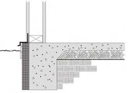
Another option is to install the insulation inside the foundation wall and between the heated slab and exterior wall. In this case insulation must extend downward to the top of the footing and then extend horizontally inward, under the slab, a distance of 4 feet toward the center of the slab. R-5 vertical insulation is required in all climates except climate zone 16, which requires R-10 of vertical insulation and R-7 horizontal insulation.
Note: The California Mechanical Code should be consulted when constructing a heated slab.

- Other Floors: Weighted average U-factor of U-0.071.
- Heated Slab Floor: A heated slab floor shall be insulated to meet the requirements of §110.8(g).
Figure 3-7: Requirements for Floor/Soffit Surfaces

§140.3(a)4, TABLE 140.3-B, C, D
Under the prescriptive requirements, exterior floors and insulated soffits must have an assembly U-factor equal to or lower than the U-factor criterion for nonresidential and hotel/motel buildings and relocatable public school buildings in TABLE 140.3-B, C, D (Table 3-9). The U-factor for exterior floors and soffits from Reference Appendices, Joint Appendix JA4 shall be used to determine compliance with the maximum assembly U-factor requirements. The Energy Code does not allow using the R-value of the cavity or continuous insulation alone to demonstrate compliance with the insulation values of JA4; only U-factors may be used to demonstrate compliance. For metal-framed floors, batt insulation between framing section may need continuous insulation to be modeled and installed on the interior or exterior to meet the U-factor requirements of the Energy Code. See Energy Code, Tables 140.3-B, 140.3-C, and 140.3-D.