
This chapter describes how the EDRs are calculated, how the proposed design is modeled, and how the standard design is established.
A lower EDR1 score represents lower source energy consumption. The EDR1 score is a metric of the proposed design source energy divided by the reference design source energy budget. An EDR1 score is calculated for the proposed design and a second EDR1 score is calculated for the standard design. The proposed design EDR1 must be equal to or less than the standard design EDR1.
An EDR2 score of zero represents a building that has zero-net-energy performance based on the TDV energy consumption, and an EDR2 score of 100 represents a building that is minimally compliant with the 2006 International Energy Conservation Code. The EDR2 score is a ratio of proposed design TDV budget to reference design TDV budget.
An Efficiency EDR2 and Total EDR2 score are calculated for the proposed design and a second Efficiency EDR2 and Total EDR2 score are calculated for the standard design. Compliance with EDR2 requires meeting two criteria:
- Proposed design Efficiency EDR2 must be equal to or less than standard design Efficiency EDR2. The EDR2 is established by the ratio of the standard design or proposed design space heating, space cooling,indoor air quality IAQ ventilation, water heating, self-utilization credit TDV energy consumption, and the reference design TDV energy consumption of the same end uses.
- Total EDR2 (Efficiency EDR2, plus PV/flexibility EDR2) of the proposed design must be equal to or less than the Total EDR2 of the standard design. The Total EDR2 is established by the ratio of the standard design or proposed design efficiency end uses plus interior lighting, appliances, cooking, plug loads, exterior lighting, and PV generation and flexibility measures TDV energy consumption and the reference design. TDV energy consumption of the same end uses.
The single-family residential building configuration is defined by the user through entries that include floor areas, wall areas, roof areas, ceiling areas, window areas, skylight areas, and door areas. The user also specifies performance characteristics such as R-values, solar heat gain coefficient (SHGC), solar reflectance, and thermal emittance are required inputs. Information about the orientation and tilt is also required for roofs, and exterior walls. Details about the HVAC and water heating systems, as well as any solar generation systems and battery storage, are also defined by the user. The user entries for all building elements should be consistent with the actual building design. If the compliance software models the specific geometry of the building by using a coordinate system or graphic entry technique, the data generated should be consistent with the actual building design.
The standard design building, from which the energy budget is established, is in the same location and has the same geometry as the proposed design, except the wall and window areas are distributed equally among the four cardinal directions (north, east, south, and west). For additions and alterations, the standard design shall have the same wall and fenestration areas and orientations as the proposed building. The details are described below.
The energy budget for the residential standard design is the energy that would be used by a building similar to the proposed design if the proposed building met the requirements of the prescriptive standards. The compliance software generates the standard design automatically, based on fixed and restricted inputs and assumptions. Custom energy budget generation shall not be accessible to program users for modification when the program is used for compliance or when the program generates compliance forms.
The basis of the standard design is prescriptive requirements from Section 150.1(c) of the Energy Code, Table 150.1-A. Prescriptive requirements vary by climate zone. Reference Appendices, Joint Appendix JA2, Table 2-1, contains the 16 California climate zones and representative cities. The climate zone is based on the zip code for the proposed building, as documented in JA2.1.1.
The following sections present the details of how the proposed design and standard design are determined. For many modeling assumptions, the standard design is the same as the proposed design. When a building has special features, for which the CEC has established alternate modeling assumptions, the standard design features will differ from the proposed design, so the building receives appropriate credit for its efficiency. When measures require verification by a Home Energy Rating System (HERS) rater or are designated as a special feature, the specific requirement is listed on the CF1R.
The reference design is calculated using the same inputs, assumptions, and algorithms as the standard design except for the following requirements:
-
Air handler power. The air handler power is 0.8 watts per cubic feet of airflow per minute (W/CFM).
-
Air infiltration rate. The air infiltration rate is 7.2 air changes per hour at 50 pascals of pressurization (ACH50).
-
Cooling airflow. The air handler airflow is 300 cubic feet of airflow per minute per ton of cooling capacity (CFM/ton).
-
Duct R-value. The duct R-value is R-8.
-
Duct leakage rate. The duct leakage rate is modeled as a heating, ventilation, and air-conditioning (HVAC) distribution efficiency of 80 percent.
-
Quality insulation installation (QII). QII is modeled as “Yes.”
-
Wall construction. Climate Zones 2–15 have 2x4 R-13 walls. Climate Zones 1 and 16 have 2x6 R-19 walls.
-
Roof/ceiling construction. Climate Zones 2–15 have R-30 ceiling. Climate Zones 1 and 16 have R-38 ceiling. No climate zones include radiant barriers or cool roofs.
-
Raised floor construction. Climate Zones 2–15 have 2x10 R-19 floors. Climate Zones 1 and 16 have 2x10 R-30 floors.
-
Slab edge insulation. Climate Zones 1 and 16 include R-10 insulation 24 inches deep.
-
Window U-factors. Climate Zones 2–15 have 0.65 U-factor. Climate Zones 1 and 16 have 0.35 U-factor.
-
Window SHGC. All windows have 0.4 SHGC.
-
Window area. When the window area is below 18 percent of the floor area, the reference design has the same area as the proposed design. Above 18 percent, the reference design has 18 percent.
-
HVAC equipment efficiencies. HVAC equipment meets National Appliance Energy Conservation Act (NAECA) requirements in effect in 2006 such as 78 percent AFUE for gas central furnace, and 13 SEER for central air conditioning.
-
Water-heating efficiency. Water heating modeled as a 40-gallon storage water with a 0.594 energy factor (EF) if gas or a 0.9172 EF if electric.
-
Appliance and plug-load energy use and internal gains. Energy use and internal gains for appliance and miscellaneous plug loads are modeled as specified the ANSI/RESNET/ICC 301-2014 Standard.
The PV requirements are applicable to newly constructed single-family residential buildings. PV system details are from PVWatts, which is a web application developed by the National Renewable Energy Laboratory. See Appendix F for more information.
Standard Design
The standard design PV system (based on California flexible installation [CFI] assumptions) is sized to generate enough electricity to offset the entire annual electricity consumption for a mixed-fuel building that meets all the 2022 prescriptive requirements.
The compliance summary tab in CBECC-Res provides energy consumption information for the building, including photovoltaic and battery systems (Figure 2: Energy Use Details).
For PV sizing calculations, the software assumes the CFI orientation 170 degrees, standard efficiency for modules, inverter efficiency of 96 percent, fixed tracking, standard (excluding horizon) shading, roof tilt of 22.61 degrees (5:12 pitch), and annual solar access percentage of 98 percent.
Proposed Design
The proposed PV system is sized to offset the entire annual electricity consumption of the proposed design.
For PV sizing calculations, the software includes user-defined values for:
- Array orientation, including CFI1 (installation of 150–270 degrees, CFI2 (installation of 105-300) or the actual orientation.
- Module type, including standard (for example, poly- or monocrystalline silicon modules), premium (for example, high-efficiency monocrystalline silicon modules with anti-reflective coatings), or thin film (in other words, low efficiency such as 11 percent).
- Inverter efficiency.
- Array tilt in degrees or roof pitch, or CFI1 or CFI2 (installation up to 7:12).
- Array tracking type including fixed, single-axis tracking, and two-axis tracking.
- Annual solar access percentage, excluding horizon shading, of the modules.
The PV size is reported in kWdc.
Figure 2: Energy Use Details
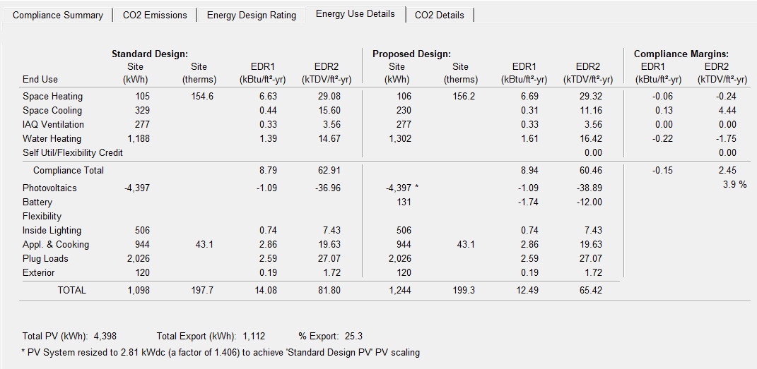
Source: California Energy Commission
For projects that use an approved Neighborhood Solar Shares (NSS) program to provide the required PV, click the “Use Community Solar” checkbox on the EDR/PV tab and select the NSS program from the drop-down list. The software will automatically use the PV characteristics of the NSS program site to size the required PV system for the building.
Figure 3: Community Solar
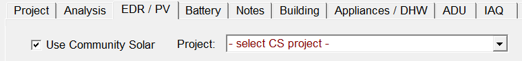
Source: California Energy Commission
• No PV system is required if the solar access roof area (SARA) is less than 80 contiguous square feet. The SARA of the building is described in Section150.1(c)14 of the Energy Code.
• No PV system is required when the minimum PV system size specified by Section150.1(c)14 of the Energy Code is less than 1.8 kWdc.
• Buildings with enforcement-authority-approved roof designs, where the enforcement authority determines it is not possible for the PV system - including panels, modules, components, supports, and attachments to the roof structure - to meet the requirements of the American Society of Civil Engineers (ASCE), Standard 7-16, Chapter 7, Snow Loads.
• For buildings that are approved by the local planning department before January 1, 2020, with mandatory conditions for approval, shading from roof designs and configurations for steep-sloped roofs, which are required by the mandatory conditions for approval, shall be considered for the annual solar access calculations and roof areas that are not allowed by the mandatory conditions for approval to have PVs shall not be considered in determining the SARA.
• PV system sizes determined using Equation 150.1-C may be reduced by 25 percent if installed in conjunction with a battery storage system. The battery storage system shall meet the qualification requirements specified in Joint Appendix JA12 and have a minimum usable capacity of 7.5 kWh.
When the solar electric generation system meets one of the prescriptive exceptions, the standard design is modeled with an appropriately sized PV system. The proposed design is modeled with a system size that does not exceed the PV size required by the standard design.
The software provides the option of specifying a PV size based on a user-specified target EDR. When this option is selected, the software calculates the required PV size based on the following parameters:
- The user-defined target EDR2
- The size of the battery storage system and the battery control strategy
- The proposed annual kWh budget of the building
Detailed calculations for PV and battery storage are included in Appendices C and D.
The software provides credit for a battery storage system coupled with a PV array. If specified, the battery storage size must be 5 kWh or larger. For Part 6 compliance, PV has no effect on energy efficiency requirements or the efficiency EDR2 unless a battery storage system is included, and the self-utilization credit is modeled.
Including a battery storage system allows downsizing the PV system to reach a specific EDR2 target.
Software includes a checkbox option to allow excess PV generation credit for above-code programs. This option, combined with a battery storage system, allows any PV size with full EDR2 credit.
The three control options available are:
- Basic (Default Control). A simple control strategy that provides a modest credit. The software assumes that the batteries are charged anytime PV generation (generation) is greater than the house load (load); conversely, the batteries are discharged when load exceeds generation. This control strategy does not allow the batteries to discharge into the grid.
- Time of Use. To qualify for the TOU control, the battery storage system shall be installed in the default operation mode to allow charging from an on-site PV system or from the utility grid if a stand-alone battery storage system. The battery storage system shall begin discharging during the highest-priced TOU hours of the day, which varies by time of the year and the local utility. At a minimum, the system shall be capable of programming three seasonal TOU schedules, such as spring, summer, and winter. This option allows discharging directly into the grid.
- Advanced Demand Flexibility Control. To qualify for the advanced demand flexibility control, the battery storage system shall be programmed by default as basic control or TOU control, as described above. The battery storage control shall meet the demand-responsive control requirements specified in Section 110.12(a). The battery storage system shall have the capability to change the charging and discharging periods in response to signals from the local utility or a third-party aggregator. Upon receiving a demand response signal from a grid operator, this option allows discharging directly into the grid.
Verification and Reporting
PV required size and battery system storage details are reported as special features on the CF1R.
The 2022 Energy Code does not allow a tradeoff between the efficiency EDR2 and the effect of PV on the total EDR2 unless battery storage is provided. When the PV system is coupled with at least a 5 kWh battery storage system, the software allows a portion of the PV/flexibility EDR2 to be traded against the efficiency EDR2. A modest self-utilization credit can be used for tradeoffs against building envelope and efficiencies of the equipment installed in the building (Table 1). A checkbox is provided in the software to enable this credit.
The magnitude of the credit is equal to the 90 percent of the difference between the 2022 and 2016 Standards envelope requirements, including:
- Below-deck batt roof insulation value of R-19 for the 2022 Standards, and R-13 for the 2016 Standard.
- Wall U-factor of 0.048 for the 2022 Standards and U-factor of 0.051 for the 2016 Standards.
- Window U-factor of 0.30 for the 2022 Standards, and window U-factor of 0.32 for the 2016 Standards.
- In cooling climate zones, window SHGC of 0.23 for the 2022 Standards, and 0.25 for the 2016 Standards.
- QII requirement in the 2022 standards, and no QII requirements in the 2016 Standards.
| Climate Zone | Single- Family |
| 01 | 13% |
| 02 | 11% |
| 03 | 11% |
| 04 | 11% |
| 05 | 13% |
| 06 | 8% |
| 07 | 6% |
| 08 | 16% |
| 09 | 13% |
| 10 | 13% |
| 11 | 13% |
| 12 | 14% |
| 13 | 12% |
| 14 | 12% |
| 15 | 11% |
| 16 | 12% |
Source: California Energy Commission
For every hour of the year, the software calculates all energy end uses in the house, including HVAC, water heating, indoor air quality (IAQ), plug loads, appliances, inside and exterior lighting, and PV generation. Based on these hourly calculations, the software calculates photovoltaic electricity generation that serves the house loads (which reduces the electricity purchased from the grid) and the hourly exports back to the grid. Next, the software applies source energy factors that represent the carbon dioxide CO2 generation characteristics of the grid to the hourly kWh balances to calculate the CO2 generation for each hour of the year. Finally, the software totals the hourly results to yield the annual CO2 emissions in metric tons per year.
The software reports CO2 generation for:
- Total CO2 generation.
- CO2 generation excluding exports to the grid (self-use only).